Estrutura para Ventiladores II
- carolineholanda
- 26 de ago. de 2019
- 4 min de leitura

"El camino de la perfección es infinito" - me diz Leo perante minha agonia por racionalmente querer parar, mas não conseguir, devido a minha expressa falta de desejo de finalizar as coisas em detrimento de manter estudos de melhorias nos processos.
Eu continuo estudando as espessuras da Joint Ball mais adequada para construir os pés dos ventiladores. Testei diferentes desingners e com diferentes medidas entre o diâmetro da cava e da bola. A pesquisa prossegue, perseguindo a cava que tem um corte e finalmente reduzindo de maneira irracional (para mim), a cava, que agora está em 15.5mm de diâmetro, com uma linha de 16mm.
Com o filamento verde-água, da Candy-ho, no dia seguinte, tem uma diminuição, um afrouxamento da noite ball.
Hoje tô testando com o filamento transparente, que trouxe do Brasil, porque o verde-água fica incrivelmente feio no ventilador. Penso que a cor mais bonita é a sugerida por Leo: branca. Mas, como não quero gastar dinheiro agora, vou tentar com esse transparente e se não der pra nada (porque ele é meio velho), vou tentar com o preto.
Algumas das variações de design foram: original; original com uma bolinha de pressão dentro; original com corte; original com corte e bolinha. E várias variações de espessuras.
Ahhh! Um aprendizado super importante: usar os "fillets" para arredondar os ângulos de 90º, sobretudo quando o ângulo está todo impresso na mesma direção e fica muito mais fácil de quebrar (o fillet aumenta um pouco a área). Lembrei de fazer isso depois que um desses "L's" maiores... Leo quebrou (como não.... um material que resiste a Leo, resiste a tudo).
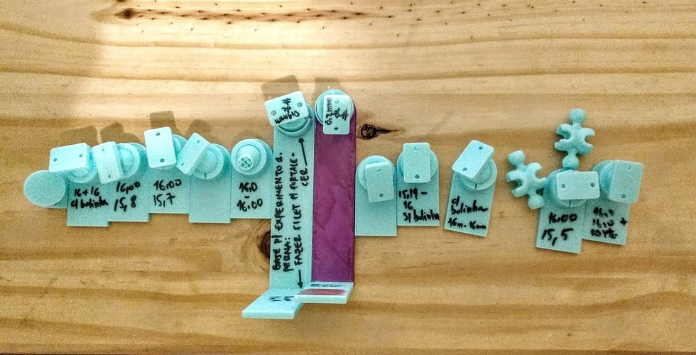


Como mencionei, elegi trabalhar sobre esse último (imagem) e ando com 15.5mm de diâmetro da cava e 16mm de cilindro. E aumentei a altura da cava de 12mm que estava (isso no desenho, não dá pra ver aqui), pra 12.1mm (quase nada, nem sei a partir de quantos milímetros faz realmente diferença).
O artigo que mais me ajudou a pensar isso e que tomei de base (inclusive imprimi e fiz umas proporções doidíssimas com as medidas que fiz com o paquímetro, foi esse (coloquei aqui, porque tudo dá erro na internete depois de um tempo...)
Ball and socket joints are a powerful way of adding mobility and functionality to your 3D designs. Creating properly fitting joints can be challenging due to the precise tolerances required. In this post, you’ll learn how to create several types of ball joints and discover recommendations for securing a proper fit.
You’ll learn about two ball joint mechanisms, those that print-in-place and those that are pressed together after printing. We’ll go through recommendations for materials that maximize the effectiveness of your joint and demonstrate a few applications.
Insertional Ball Joint
This type of ball joint prints in two separate parts and snaps together after printing. Tolerances for this type of joint can be especially challenging as too tight of a fit won’t allow the ball to enter the socket and too loose of a fit will allow the ball to fall out easily.
We’ll be using the graphic below which was designed in Onshape to demonstrate some of the main parameters to keep in mind when creating this type of ball joint.
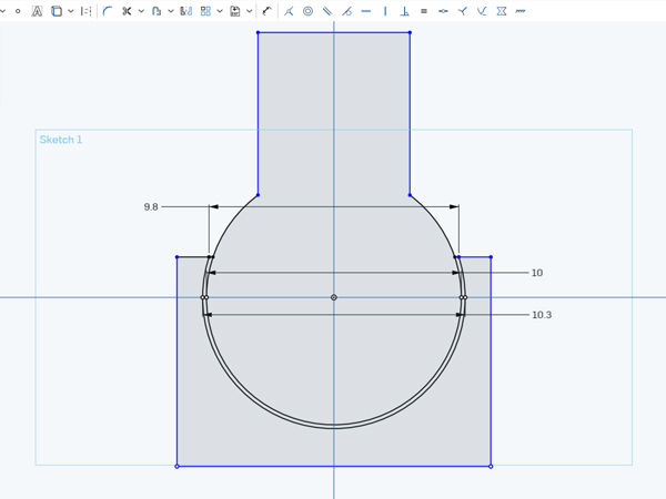
For a normal joint, the offset between the ball and socket should be about 0.3mm. Ex: In the image above, the ball has a diameter of 10mm and the socket has a diameter of 10.3mmFor a tight fit, the opening of the socket should be 0.2mm smaller than the diameter of the ball. Ex: The socket opening is 9.8mm and the diameter of the ball is 10mm.
When creating a ball and socket joint, iteration is key and the above values may change depending on your application. Ball joints much larger or much smaller than the example above will require changes to the dimensions, but these are good guidelines for starting out.
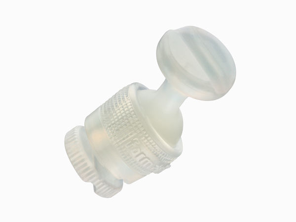
The dimensions listed above were used to create Formlabs’ Durable Sample part which is a great illustration of a functional ball joint and demonstrates the low-friction properties of Durable Resin. You can grab one for free here to test out the tolerances for yourself
Print-in-Place Ball Joint
This type of joint is a favorite among talented designers like Sonia Verdu and you can find many examples of a print-in-place ball joint on her page. As the name suggests, this type of joint prints with the ball and socket as one piece and if done correctly, is fully functional after printing.
Tolerances for this type of joint can be more challenging as if the walls of the ball and socket are too close, they’ll fuse together rendering your joint useless.

The part must be oriented such that the highest point of the socket is above the highest point of the ball. Unsupported minima will cause the socket to fail. This technique makes use of overhangs so adequate layer cooling is required on FDM machines.For SLA printers, the offset between the ball and socket should be 1.25mm. For FDM machines, the offset between the ball and socket should be 0.8mm. Ex: In the image above, the diameter of the ball is 10mm and the socket is 11.25mm for SLA printing.The diameter of the socket opening must be smaller than the diameter of the ball. Ex: The socket opening is 9mm across and the diameter of the ball is 10mm.
This technique can be challenging to get right and thanks to the Formlabs Forums for discovering the best tolerances for SLA printing. If you’re noticing that the walls are fusing together, continue adjusting tolerances until you have a proper fit. This technique is optimal for creating loose-fitting joints and doesn’t work well for designs where a tight fit is required.
Material Options
Ball and socket joints are constantly in motion and sliding against each other so a low-friction material is required. For professional quality joints, Durable Resin by Formlabs is the best option. This material mimics polypropylene and has low-friction properties as well as moderate elongation which makes it especially well suited for ball jointed designs.

Few FDM materials exist that compete with the low-frictional properties of Durable Resin, but many materials will still work for ball-jointed designs. The lowest friction materials for FDM are Polycarbonate Filament and Tribo Filament by Igus, but these can be costly and challenging to use. For non-professional applications, more common materials like PLA and ABS are likely to work.
With these design and material guidelines in mind, you’re ready to start implementing ball joints into your own designs. For inspiration check out Sonia Verdu’s and BQ’s design pages where they host a number of impressive ball-jointed designs.


Comentários